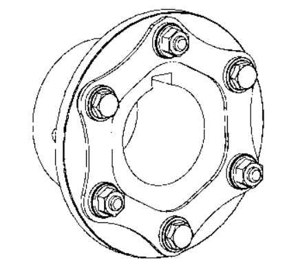
The following is really a sample application employed to illustrate the typical method for selecting a Disc coupling. Any resemblance to any existing company?¡¥s application is neither intentional nor meant to resemble that company?¡¥s real application.
Sample Application:
A company features a compressor application employing a 225 horsepower electric motor running at one,150 RPM to drive a 3 cylinder multi stage reciprocating air compressor. The electrical motor includes a 3-3/8 inch shaft that has a 7/8 inch keyway along with the compressor includes a 92mm shaft having a 25mm keyway. The shaft separation is approximately seven inches involving shaft ends with some means to change the motor spot. The shafts have a parallel misalignment/offset of approximately 1/32 of an inch.
Stage 1: The first phase would be to determine what coupling style is to be selected for this application. Because the SU Style coupling only supports
just one flex plane, it may only accommodate angular and axial misalignment, but not parallel misalignment. The subsequent selection can be to seem at an SX or DI Variety coupling. The six bolt SX Variety will accommodate the two parallel misalignment and also the defined shaft separation. The dimension are going to be established by the selection torque along with the shaft diameters.
Phase 2: Up coming, calculate the application torque and apply the support issue to calculate the choice torque.The formula employed to determine torque is as follows:
Application Torque ( in¡§Clb ) = ( HP x 63025 )/RPM
or Nm = ( KW x 9550)/RPM
Plugging during the numbers through the application description:
Application Torque ( in-lbs ) =(HP x 63025)/RPM = (225 x 63025)/1150 = 12,331 in-lbs
Application Torque x Services Component = Choice Torque
twelve,331 in-lbs x three.0 = 36,993 in-lbs
Stage 3: Use the SX coupling tables and note that the SX 202-6 is rated at 40,700 in-lbs, greater than enough to take care of the selection torque calculated in stage two. The SX202-6, having said that, will not support the 92mm shaft size. The next greater dimension coupling, the SX228-6, will help the 92mm shaft size and the shaft separation dimension (BSE) is 6.88 inches, quite close to the application?¡¥s desired 7 inch separation. The SX228-6 is rated at 62,000 in-lbs which may possibly seem to be excessive, however, the  coupling dimension is necessary to manage the bore dimension.
Step four: The SX228-6 coupling is rated for a greatest unbalanced speed of three,400 RPM, more than sufficient to support the application pace of 1,150 RPM.
Phase 5: To find out in case the coupling will manage the parallel misalignment, utilize the trig function of tan 1?? = offset allowed for one inch = 0.0174
Multiply the 0.0174 x the distance amongst disc packs or ??S?¡¥ dimension from your table on page D-13, or 5.50 inches.
The allowable parallel offset is 0.0174 x five.50 = 0.096 inches. The utmost offset for your application is 1/32 inches (0.031), thus this coupling can accommodate the parallel misalignment.
Note: It can be normally encouraged to make an effort to set up the coupling at approximately 20% on the allowable misalignment. For this coupling the installer need to try to attain much better than 0.020 parallel misalignment with the time of installation. This will enable to the added misalignment that can come about as the result of tools settle and common gear dress in.